 While a solar PV system may appear to be producing free
electricity from the sun and operating properly, it may also have inherent
safety and performance problems. It’s therefore important for
the DIY installer and others to understand the basics of solar PV safety
and performance. The PV charge controller is a critical component of a PV system. It can easily be damaged and have poor performance without the owner’s awareness. Many experience PV installers will provide an additional digital readout with multiple voltage and amp-hour readings that can monitor system and controller performance. Not only are these cool to view and monitor your PV solar intake/output/usage; they can also indicate decreasing or poor performance and prompt you to take action that may substantially increase your onsite solar production and save you more money. _________________________________________________________ The amount of power a wire can safely carry is related to how hot it can safely get. Wires have resistance and as power flows through them, that resistance causes heat to build up. The more power you put through a wire, the hotter it gets. Insulation breaks down when it gets too hot, and at some point it will melt away; leaving the wire exposed to whatever is around it – possibly causing a fire. Please do not scrimp on wire size. Wire size matters in a PV system. When in doubt, increase the wire (diameter) size. It’s a worthy investment. Properly sized wire can make the difference between inadequate or full charging of a battery system – between dim and bright lights. The size of wires between your PV solar panels and charge controller are critical to efficient system operation and in obtaining maximum energy flow. At worse, improperly sized wires can create a fire hazard. If you have ever plugged in a portable electric heater in the wintertime and felt how hot its electrical cord is, you’ll have first hand experience with how hot an electrical wire can get. Even though Solar PV systems generate low-voltage, there’s a lot of power in 12VDC! Don’t let the ‘low’ fool you. Look at the size of the battery cable in your car – that’s roughly the size of the wire you’ll need from your PV panel array to your controller and batteries. There is less tolerance for voltage drop in low-voltage PV systems than in typical household 120/240 volt systems: A 1 volt drop in a 12VDC PV system amounts to an 8.3% drop. A 1 volt drop in a 120 VAC system amounts to a 0.83% drop. The accepted formula for calculating DC wiring size is as follows:
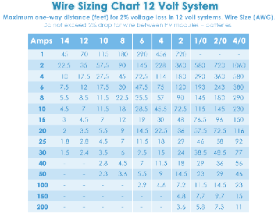
When sizing wiring for pumps and motors (and appliances that use them) be sure to consult the manufacturer’s recommendation for surge amperage needs of the pump or motor. Here is a typical wiring chart for a 12 volt, 2% loss solar PV system.
For more information on how to
size electrical wiring, contact an electrical engineer or contractor. Solid or Stranded wire? Without getting into the science of how electricity flows through wire, this question is best answered from a practical standpoint: breakage. Always use stranded wire. If one strand breaks in stranded wire, there are still many other strands left to do the job. If one strand breaks in solid wire, you have an open circuit and system failure. Even though your household uses solid wire, please use stranded wire for your solar PV system. This (which includes lightning strikes) is one of the most confusing issues in electrical systems and in PV installations. The word grounding means different things to different people. The NEC® (National Electric Code) has specific requirements for grounding of solar PV systems (NEC Section 690-13, 15 etc). The word GROUNDED means connected to the earth. The NEC requires one conductor (normally the negative) of a two conductor PV system above 50 VDC to be grounded. Any PV system with three conductors (positive, negative, neutral) must have the neutral grounded. Grounding exposed metal surfaces creates a barrier between the live conductors and a person – this is good thing! In a PV system with proper over-current protection devices, the ground provides a mechanism to trip or blow over-current protection devices in case of an electrical fault. An additional advantage of properly grounding inverters, fluorescent lights, etc. is less radio/TV/tele-data reception interference. The simplest grounding system has a properly sized grounding wire (usually green) connected to ONE grounding rod (preferably driven deep into the soil). This grounding wire must be common to all systems. Both AC and DC systems’ grounds must be kept separate and NEVER be tied together. All solar PV arrays and related controllers, regulators and other DC circuitry must be tied to one ground. If you are on a utility grid, your AC wiring is already grounded through the utilities’ system, so there is no need for a separate ground. Do not tie your PV system to the utility system’s ground! Having multiple DC grounds may cause stray ground loops to be set up, which are whole different bag of worms – consult an electrical engineer for more information about potential problems with ground loops. There should be no splices in the grounding wire.
 |


